

An EV battery copper busbar is a critical electrical interconnection that influences current distribution, temperature rise, packaging efficiency, and long-term battery pack reliability. This guide explains how to select copper materials, determine conductor dimensions, evaluate rigid and flexible busbars, manage connection resistance, specify plating and insulation, and avoid common manufacturing problems. It also provides a practical sourcing checklist to help engineers and procurement teams develop custom busbars that meet their electrical, mechanical, and production requirements.
1. What Is an EV Battery Copper Busbar?
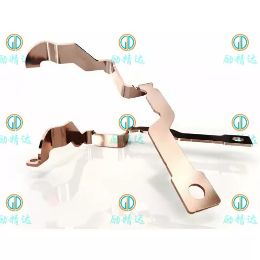
An EV battery copper busbar is a conductive metal component designed to transfer electrical energy between battery cells, modules, contactors, fuses, current sensors, and other components within an electric vehicle's high-voltage system. Depending on the battery architecture, busbars can be flat strips, formed plates, laminated flexible conductors, or specially shaped assemblies manufactured to precise dimensional requirements.
Unlike conventional wiring, a busbar can provide a compact, repeatable current path with defined contact surfaces and mounting positions. This makes it particularly useful in battery packs where available space is limited and electrical connections must remain stable under vibration and temperature changes.
A typical EV battery system may contain several busbar levels:
- Cell interconnections: Connect individual cells or groups of cells within a module.
- Module connections: Transfer current between battery modules and support the required series or parallel configuration.
- Pack-level busbars: Connect modules to high-voltage distribution components, including contactors, fuses, and output terminals.
- Power electronics connections: Link battery systems with inverters, DC distribution assemblies, or other high-current equipment.
The specific design depends on the cell format, system voltage, current profile, connection method, available installation space, and safety requirements. A successful busbar is therefore more than a piece of copper: it is an engineered component that must work as part of the complete electrical and mechanical assembly.
2. Why Does Copper Matter in EV Battery Systems?
Copper is widely used for high-current battery interconnections because it combines high electrical conductivity with good thermal conductivity, formability, and compatibility with many established fabrication and surface-finishing processes.
These characteristics help engineers develop compact current paths while controlling electrical losses and supporting reliable connections. However, copper alone does not guarantee good performance. Dimensions, joints, cooling conditions, insulation, and manufacturing quality must also be considered.
Lower electrical resistance
Electrical resistance produces heat when current passes through a conductor. A properly dimensioned copper busbar can limit resistive losses and voltage drop, helping preserve power transfer efficiency. The benefit is particularly relevant in high-current battery systems, where even a small resistance increase may create a meaningful amount of heat.
Compact electrical packaging
Battery packs must accommodate cells, cooling components, structural supports, sensors, protective devices, and insulation within a limited enclosure. Copper's high conductivity allows designers to evaluate relatively compact conductor cross-sections while meeting the required electrical and thermal limits.
Adaptable fabrication
Copper sheets, strips, and bars can be cut, stamped, punched, bent, machined, and plated according to the component design. Depending on the application and manufacturing capability, these processes can produce customized hole patterns, formed terminals, mounting features, and complex three-dimensional shapes.
Potentially improved assembly consistency
A well-designed custom busbar provides repeatable connection locations and mounting geometry. This can simplify automated or semi-automated assembly, reduce installation adjustments, and help improve production consistency.
3. Which Busbar Structure Fits Your Application?
Choosing the right structure is an important early decision because it affects installation space, flexibility, vibration tolerance, fabrication methods, and overall project cost. The most common options include rigid copper busbars, laminated flexible busbars, and braided copper connections.
| Busbar Type | Typical Application | Main Advantages | Key Considerations |
|---|---|---|---|
| Rigid copper busbar | Fixed module connections and high-voltage distribution | Stable geometry, compact routing, repeatable mounting | Limited movement; bend accuracy and installation tolerances matter |
| Laminated flexible busbar | Compact battery modules and connections affected by thermal movement | Flexible connection zones and low-profile packaging | Layer construction, terminal bonding, and bend-zone design require control |
| Braided copper connector | Connections requiring greater movement or vibration accommodation | High flexibility and adaptable routing | Terminal joining, exposed conductor protection, and mounting space |
| Custom formed busbar | Restricted spaces and complex component layouts | Geometry tailored to the assembly and connection points | Tooling, springback, dimensional tolerances, and inspection access |
When is a rigid busbar appropriate?
A rigid design is suitable when the terminals remain in fixed positions and the mounting structure provides adequate support. It can be particularly practical for pack-level power distribution, fuse connections, and compact electrical assemblies where consistent geometry is important.
When should you consider a flexible busbar?
A flexible design may be preferable when the connection must accommodate thermal expansion, manufacturing tolerances, or relative movement between components. Laminated copper busbars can combine high-current capacity with a controlled flexible region, although the terminal areas and insulation transitions still require careful engineering.
Before selecting either structure, evaluate the full installation envelope, movement requirements, assembly sequence, service access, and electrical load. A design that fits a CAD model may still be difficult to install if tool access, fastener clearance, or production tolerances have not been considered.
4. How Should You Select Copper Materials?
Material selection affects conductivity, forming behavior, joining compatibility, surface treatment, and cost. The appropriate grade depends on the manufacturing process and operating environment rather than on copper purity alone.
| Material Option | General Characteristics | Potential Application | Selection Considerations |
|---|---|---|---|
| C11000 / ETP copper | High electrical conductivity and good general-purpose formability | Many rigid busbars and bolted electrical connections | Confirm grade, temper, forming requirements, and joining process |
| C10200 / oxygen-free copper | High conductivity with low oxygen content | Applications with specific material purity or joining requirements | Evaluate the actual welding, brazing, and thermal process |
| T2 copper | Common copper designation in relevant supply chains | Custom copper strips, plates, and fabricated busbars | Confirm the applicable material standard and equivalent grade requirements |
| Copper alloy | Properties vary by alloy; some grades offer increased strength | Specialized contacts or applications with additional mechanical demands | Conductivity may be lower than that of high-conductivity copper |
Consider temper and forming requirements
Material temper affects strength, ductility, bendability, and springback. A tight bend in thick copper may cause surface cracking or distortion if the material condition and bend radius are unsuitable. When a design contains several bends or closely positioned holes, a manufacturing review can identify risks before tooling or mass production begins.
Match the material to the joining method
Bolted, welded, brazed, and laminated structures impose different requirements. For example, a copper grade that works well for a conventional bolted connection may not be the best option for a specialized welding process. The supplier and design engineer should confirm material compatibility with the intended joining method and validate the finished joint where necessary.
For international sourcing, specify the required material standard, grade, temper, thickness, and allowable substitutions. A general note such as “high-quality copper” is insufficient when electrical performance and repeatable production must be verified.
5. How Do Current, Resistance, and Heat Affect Design?
Current capacity is one of the most important factors in EV battery busbar design. However, there is no universal current rating that applies to every copper strip of a particular width and thickness. Actual performance depends on conductor geometry, ambient temperature, enclosure conditions, cooling, connection resistance, and the duration of the electrical load.
Understand the basic electrical relationships
For a DC system, current can be estimated from power and voltage:
Conductor resistance: R = ρL / A
Resistive power loss: Ploss = I²R
In these relationships, I is current, P is electrical power, V is voltage, R is resistance, ρ is material resistivity, L is conductor length, and A is cross-sectional area. The equations provide a starting point for design calculations, not a substitute for thermal analysis or testing.
The squared-current term is especially important. If current doubles while resistance remains unchanged, resistive power loss increases by a factor of four. This makes current profile, duty cycle, and connection quality critical considerations.
Evaluate continuous and peak current separately
EV battery systems may experience continuous discharge, short acceleration peaks, regenerative braking, and charging loads. These operating conditions can create different thermal demands. A design that tolerates a brief peak may not be suitable for the same current applied continuously.
Engineers should define the following before finalizing conductor dimensions:
- Rated system voltage and maximum operating voltage.
- Continuous current, peak current, and peak duration.
- Ambient temperature near the busbar and the expected operating temperature range.
- Allowed temperature rise at both the conductor and connection points.
- Conductor length, available cross-section, and installation orientation.
- Cooling conditions, neighboring heat sources, and enclosure ventilation.
- Maximum allowable voltage drop and relevant protection requirements.
Do not overlook the complete thermal path
Heat may leave a busbar through convection, radiation, mounting hardware, connected terminals, or nearby structures. Insulation and a sealed enclosure can change heat dissipation. As a result, two busbars with identical copper dimensions may reach different temperatures in different assemblies.
A robust development process combines calculation, engineering review, and testing under representative conditions. For safety-critical applications, temperature-rise validation should reflect the intended materials, surface treatment, fastening method, and installation environment.
6. How Can You Prevent Connection Failures?
A high-quality copper conductor can still fail to deliver reliable performance if its connections are poorly designed. At high current, excessive contact resistance can generate localized heat, accelerate surface degradation, damage nearby insulation, or contribute to joint loosening.
Design contact surfaces carefully
Bolted joints require suitable contact area, surface flatness, fastener selection, and controlled clamping force. Hole position, burrs, deformation, contamination, and incompatible surface finishes can all affect the final interface. The assembly specification should define the relevant bolt torque or fastening procedure rather than leaving it to individual operator judgment.
Control welded and laminated connections
Flexible laminated busbars often use bonded or welded terminal zones to connect multiple copper layers. The joint must provide adequate electrical continuity and mechanical integrity without damaging the flexible section. Welding parameters, terminal geometry, heat input, and inspection methods should be established for the actual material stack.
Plan for vibration and thermal cycling
Electric vehicles operate under repeated vibration and temperature changes. Differences in thermal expansion between connected components can place stress on busbars and fasteners. Flexible sections, suitable supports, appropriate clearances, and qualified joining methods can help accommodate these conditions.
| Potential Problem | Possible Consequence | Preventive Measure |
|---|---|---|
| Excessive contact resistance | Localized heating and increased power loss | Review contact geometry, surface finish, and fastening controls |
| Incorrect hole position | Assembly difficulty or uneven contact pressure | Set functional tolerances and inspect critical dimensions |
| Cracking at a bend | Reduced mechanical integrity or electrical continuity | Validate material temper and bend radius |
| Poor weld quality | Unstable resistance or mechanical separation | Qualify the joining process and define inspection criteria |
| Fastener loosening | Changing contact resistance during service | Use an appropriate fastening design and assembly procedure |
7. How Do Plating and Insulation Improve Safety?
Surface treatment and insulation are functional design decisions, not merely cosmetic finishing options. They can affect contact behavior, corrosion resistance, electrical isolation, assembly consistency, and service safety.
Choose plating for the contact environment
Tin, nickel, and silver plating may be used in different busbar applications. Tin is commonly considered for many electrical contact interfaces because of its cost and practical contact characteristics. Nickel may be appropriate for certain temperature or environmental requirements, while silver can be considered where its electrical contact properties justify the additional cost.
The final selection must consider the mating terminal, operating temperature, humidity, contamination, corrosion exposure, contact pressure, and applicable product requirements. Plating thickness, coverage, masking, and inspection criteria should be specified where they affect functionality.
Specify insulation according to system voltage
Depending on the design, busbars may use heat-shrink tubing, polymer sleeves, molded covers, epoxy coatings, or other engineered insulation systems. Each solution has different requirements for temperature resistance, dielectric performance, mechanical protection, and manufacturability.
High-voltage assemblies also require appropriate creepage and clearance distances. These distances depend on the applicable safety framework, working voltage, insulation arrangement, environmental conditions, and product construction. They should be established by the responsible design engineer rather than selected from a generic busbar chart.
Insulation must also be compatible with bends, contact windows, fastening areas, and assembly tools. Poorly defined exposed-metal areas can lead to inconsistent manual trimming, accidental damage, or reduced electrical protection.
8. What Manufacturing Processes Ensure Consistent Quality?
Manufacturing quality depends on how well the material, tooling, forming sequence, surface finishing, and inspection plan work together. The most appropriate process depends on component geometry, material thickness, tolerance requirements, prototype quantity, and expected production volume.
Step 1: Design and manufacturability review
Before production, the manufacturer should review the drawing, material specification, hole locations, bend geometry, contact areas, plating zones, and insulation requirements. This review helps identify features that may increase cost or create quality risks.
Step 2: Material preparation and cutting
Copper sheet, strip, or bar is prepared according to the approved material specification. Laser cutting, punching, stamping, CNC machining, or other suitable methods may be selected based on the required geometry and production economics.
Step 3: Forming and dimensional control
Bending and forming operations establish the final geometry. Material springback, bend radius, tooling accuracy, and hole-to-bend relationships can affect assembly fit. Critical dimensions should be identified before the inspection plan is finalized.
Step 4: Joining and surface finishing
Depending on the design, the component may require welding, terminal bonding, deburring, plating, cleaning, or insulation. Each operation should be compatible with the selected copper grade and the intended operating environment.
Step 5: Inspection and validation
A suitable quality plan may include the following checks:
- Material certificates and incoming material verification.
- Dimensional inspection of thickness, width, hole locations, bend angles, and flatness.
- Visual inspection for cracks, burrs, scratches, and surface defects.
- Plating thickness and coverage checks where specified.
- Electrical resistance or continuity checks.
- Joint strength, temperature-rise, insulation, or environmental testing when required by the project.
Not every component requires every test. The inspection plan should be based on the part's function, customer requirements, applicable standards, and risk assessment. Where automotive production controls or formal qualification documents are required, these expectations should be agreed upon before mass production.
9. How Can Buyers Reduce Sourcing Risks?
For procurement teams, the main challenge is obtaining a component that meets the engineering requirements at a competitive total cost. A quotation based only on copper weight or external dimensions may omit essential manufacturing and validation requirements.
Prepare a complete request for quotation
A clear RFQ helps the manufacturer evaluate the design, identify production risks, and quote the appropriate process. Whenever possible, provide a 2D engineering drawing and a 3D CAD file together with the following information.
| RFQ Requirement | Information to Provide | Why It Matters |
|---|---|---|
| Application | EV battery pack, module, power distribution unit, or related equipment | Defines operating conditions and functional requirements |
| Electrical load | Voltage, continuous current, peak current, duty cycle | Supports electrical and thermal evaluation |
| Material | Copper grade, temper, thickness, and any approved equivalents | Influences performance, formability, and material cost |
| Dimensions | 2D drawing, 3D model, tolerances, holes, bends, and mounting interfaces | Allows manufacturability review and accurate quotation |
| Surface treatment | Plating type, thickness, coverage, and masking areas | Determines finishing cost and contact requirements |
| Insulation | Material, coverage, thickness, color, and electrical requirements | Supports safety and production planning |
| Quantity | Prototype quantity, pilot order, and forecast annual demand | Helps determine tooling and production methods |
| Quality documents | Inspection reports, material certificates, test requirements, and traceability | Aligns acceptance criteria with project needs |
Evaluate total cost, not just unit price
The purchase price is only one part of the total cost. Tooling, material utilization, secondary processing, plating, insulation, inspection, packaging, lead time, and engineering changes can all affect project economics.
A supplier offering a lower initial price may not be the most economical choice if the part requires repeated adjustments or produces inconsistent assembly results. Conversely, unnecessary tight tolerances, excessive plating coverage, or overly complex geometry can increase cost without providing a meaningful functional benefit.
Review supplier capabilities before production
Ask prospective manufacturers how they control material consistency, critical dimensions, burrs, bends, plating, and finished-part traceability. Request samples or inspection records where appropriate, and agree on acceptance criteria before committing to a large order.
For buyers developing customized metal components, Xiamen Lijingda Hardware Products Co., Ltd. can be included in the supplier evaluation process for relevant hardware and precision metal product requirements. Before placing an order for an EV battery copper busbar, confirm the company's specific busbar manufacturing capabilities, material options, available joining and finishing processes, quality documentation, and experience with the intended application.
The most effective sourcing process brings engineering and purchasing teams together early. When the electrical requirements, drawings, production method, and acceptance criteria are aligned before quotation, both sides can reduce avoidable revisions and improve the transition from prototype to production.
10. Frequently Asked Questions
1. What is the main purpose of an EV battery copper busbar?
Its primary purpose is to transfer electrical current between battery cells, modules, and high-voltage components. A properly designed busbar supports low electrical losses, controlled temperature rise, compact packaging, and reliable electrical connections.
2. Why is copper commonly used instead of aluminum?
Copper offers higher electrical conductivity at the same cross-sectional area, along with good thermal conductivity and established fabrication options. Aluminum may provide weight and material-cost advantages, but it generally requires a larger cross-section for comparable electrical resistance and careful attention to oxide layers and dissimilar-metal connections. The best material depends on system requirements.
3. How do I determine the correct copper busbar thickness?
Thickness cannot be selected from current alone. Engineers must evaluate current profile, conductor width and length, cooling conditions, enclosure temperature, contact resistance, allowable temperature rise, and available installation space. Calculations should be followed by validation appropriate to the application.
4. Are rigid copper busbars suitable for high-vibration environments?
Rigid busbars can be used in vehicle systems when mounting, support, clearance, and joint design account for the expected mechanical loads. Where relative movement or thermal expansion is significant, a laminated flexible busbar or braided connection may be more appropriate.
5. Which plating is best for an EV battery copper busbar?
There is no universal best option. Tin, nickel, silver, or an unplated surface may be appropriate depending on the mating material, operating temperature, corrosion exposure, contact requirements, and cost target. The specification should identify the selected finish and any required thickness or coverage.
6. What causes a copper busbar to overheat?
Common causes include an insufficient conductor cross-section, excessive current, inadequate heat dissipation, high contact resistance, poor fastening, defective welds, or unsuitable operating conditions. Measuring temperatures at both the conductor body and connection points can help identify the source.
7. What files should I send to a busbar manufacturer for a quotation?
Ideally, provide a dimensioned 2D drawing, a STEP or equivalent 3D CAD model, material and surface-finish requirements, electrical operating conditions, annual demand, and inspection requirements. If the design is still under development, a preliminary drawing and application description can help initiate a manufacturability review.
8. What quality checks are important for a custom EV battery busbar?
Typical checks include material verification, dimensional inspection, visual examination, burr control, plating verification, and electrical continuity or resistance testing. Depending on the application, joint-strength, temperature-rise, insulation, vibration, or environmental testing may also be required.
9. Can EV battery copper busbars be customized?
Yes. Custom designs can specify conductor dimensions, hole patterns, bend angles, terminal geometry, plating, insulation, and other functional features. Feasibility depends on the supplier's actual equipment, material range, joining methods, tooling capabilities, and quality controls.
10. How can I reduce the cost of a custom copper busbar?
Provide complete specifications, avoid unnecessary tolerances, optimize hole and bend layouts, select an appropriate manufacturing method for the order quantity, and define functional plating and insulation zones clearly. Cost reductions should never compromise current capacity, thermal limits, insulation safety, or required joint reliability.
Develop Your Custom EV Battery Copper Busbar Solution
Reliable battery interconnections begin with the right material, accurate dimensions, suitable surface treatment, and a manufacturing process aligned with the application's electrical and mechanical requirements.
Whether you are developing a new battery module, improving an existing power distribution assembly, or sourcing precision metal components for an electric vehicle project, early communication can help clarify technical requirements and reduce unnecessary production revisions.
Xiamen Lijingda Hardware Products Co., Ltd. welcomes inquiries about relevant customized hardware and metal component projects. Share your drawings, material requirements, target quantities, and application details so the appropriate manufacturing capabilities can be evaluated.
Ready to discuss your next project? Contact us to start a conversation about your component requirements and explore a suitable path from design review to production.